You may also want to give additional thought to how you arrange your power districts. Instead of thinking geography, think utilization. Instead of dividing up your layout into districts that make physical sense on the benchwork, divide it up by where the action happens and the effect upon traffic flow.
Imagine a layout that is one big oval with a yard somewhere along its circumference. The best arrangement for this hypothetical layout would be a main district and a yard district. The yard is not affected if something shorts on the main. Conversely, trouble in the yard doesn't shut down the main. The main district wiring would run all the way around the oval while the yard district wiring would be in one small confined area. Makes no sense compared to the benchwork but makes a lot of sense compared to utilization and traffic flow.
Let's add an industrial switching area on the oval opposite the yard. Where does it get power? Ideally, you would add a 3rd district for the switching area. But to keep costs in check you could put it on the yard district. This arrangement keeps the main going if there is trouble in the yard or at the industrial switching. As the track plan grows more complex so does the district arrangement. It is very possible to have many different district wirings running together along the benchwork.
An additional consideration is trains in operation. The CB-1 comes only in a single amperage rating. Ring doesn't specify the trip current (or least I've never seen it stated) but it is a safe bet it is less than 4 amps since a PWR-56 is a 4 amp unit. Assuming you aren't running decades old equipment, 4 amps is about a dozen HO locomotives. Since the CB-1 trip point has to be a bit below the PWR-56 trip point, let's say 10 HO locos max. No single power district may have more than 10 locos on it. Less if you have keep-alives installed. Power districts have to be properly sized to the max expected electrical load, not their physical shape or location in the room.
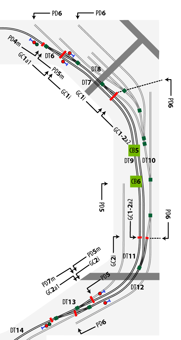
Here is an example from my layout. Ignore most of the markings. Look at the PD5/6 and CB5/6 labels.

The two green CB squares are where the circuit breakers are physically located. CB5 powers PD5 which is the main (track in black). CB6 powers PD6 which is the industrial switching area (track in gray). Note the switching lead off the main near the bottom of the drawing. This lead is on PD5 even though it is not a main track. The logic here is if you are switching this lead then you are already fouling the main. A separate district for the lead would be of no traffic-flow value. Worse yet would be the lead wired to PD6. Now if you short while switching the lead you also shut down the guy that is working the industrial area. I hope this illustrates what I mean by think utilization, not geography.