Author Topic: Getting ready to install power wiring on the layout  (Read 1761 times)

faithie999

  • Conductor
  • ****
  • Posts: 163
Getting ready to install power wiring on the layout
« on: January 08, 2021, 02:00:33 PM »
I have my benchwork completed, layout design is underway, and I'm ready to run power bus lines.  The benchwork is a "J" shape, and the linear dimension is about 45 feet overall.  I was thinking about splitting the layout into 2 districts, with a 5 amp breaker protecting each district.  I plan to use some spare Romex 12 gauge wire, which I will remove from the Romex jacket.  Alan has recommended a 15v 10A power supply which I have ordered.  I will use 5A Blue Sea (marine and RV supplier) breakers, which are rated up to 32V DC.

any opinions and recommendations are welcome!

ken


Alan

  • Conductor
  • ****
  • Posts: 1073
    • LK&O Railroad
Re: Getting ready to install power wiring on the layout
« Reply #1 on: January 08, 2021, 03:31:37 PM »
Blu Sea breakers are not suitable for a model railroad. They are conventional toggle thermal type circuit breakers. Their trip time is much too slow as evidenced on the below graph from their website. You will find all thermal type breakers, including fuses, to be too slow. Nature of the beast.

breaker.PNG

You need fast acting electronic breakers. Ring sells the RP CB-1 https://www.ringengineering.com/CB-1.htm or you can roll your own https://www.analog.com/media/en/technical-documentation/data-sheets/lt1153.pdf.
Alan

LK&O Railroad website

When I was a kid... no wait, I still do that. HO, 28x32, double deck, 1969, RailPro

faithie999

  • Conductor
  • ****
  • Posts: 163
Re: Getting ready to install power wiring on the layout
« Reply #2 on: January 08, 2021, 04:18:16 PM »
Alan--thanks for the heads-up.  I've just ordered 2 CB-1's.


Ken

Alan

  • Conductor
  • ****
  • Posts: 1073
    • LK&O Railroad
Re: Getting ready to install power wiring on the layout
« Reply #3 on: January 08, 2021, 06:44:24 PM »
You may also want to give additional thought to how you arrange your power districts. Instead of thinking geography, think utilization. Instead of dividing up your layout into districts that make physical sense on the benchwork, divide it up by where the action happens and the effect upon traffic flow.

Imagine a layout that is one big oval with a yard somewhere along its circumference. The best arrangement for this hypothetical layout would be a main district and a yard district. The yard is not affected if something shorts on the main. Conversely, trouble in the yard doesn't shut down the main. The main district wiring would run all the way around the oval while the yard district wiring would be in one small confined area. Makes no sense compared to the benchwork but makes a lot of sense compared to utilization and traffic flow.

Let's add an industrial switching area on the oval opposite the yard. Where does it get power? Ideally, you would add a 3rd district for the switching area. But to keep costs in check you could put it on the yard district. This arrangement keeps the main going if there is trouble in the yard or at the industrial switching. As the track plan grows more complex so does the district arrangement. It is very possible to have many different district wirings running together along the benchwork.

An additional consideration is trains in operation. The CB-1 comes only in a single amperage rating. Ring doesn't specify the trip current (or least I've never seen it stated) but it is a safe bet it is less than 4 amps since a PWR-56 is a 4 amp unit. Assuming you aren't running decades old equipment, 4 amps is about a dozen HO locomotives. Since the CB-1 trip point has to be a bit below the PWR-56 trip point, let's say 10 HO locos max. No single power district may have more than 10 locos on it. Less if you have keep-alives installed. Power districts have to be properly sized to the max expected electrical load, not their physical shape or location in the room.

Here is an example from my layout. Ignore most of the markings. Look at the PD5/6 and CB5/6 labels.


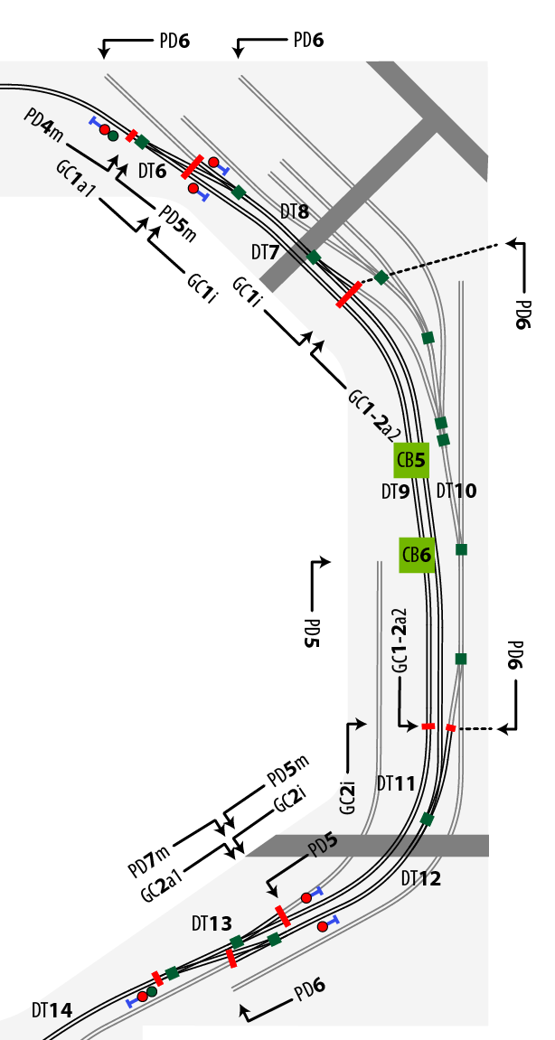
The two green CB squares are where the circuit breakers are physically located. CB5 powers PD5 which is the main (track in black). CB6 powers PD6 which is the industrial switching area (track in gray). Note the switching lead off the main near the bottom of the drawing. This lead is on PD5 even though it is not a main track. The logic here is if you are switching this lead then you are already fouling the main. A separate district for the lead would be of no traffic-flow value. Worse yet would be the lead wired to PD6. Now if you short while switching the lead you also shut down the guy that is working the industrial area. I hope this illustrates what I mean by think utilization, not geography.
« Last Edit: January 08, 2021, 06:48:43 PM by Alan »
Alan

LK&O Railroad website

When I was a kid... no wait, I still do that. HO, 28x32, double deck, 1969, RailPro

Alan

  • Conductor
  • ****
  • Posts: 1073
    • LK&O Railroad
Re: Getting ready to install power wiring on the layout
« Reply #4 on: January 08, 2021, 06:45:58 PM »
Alan--thanks for the heads-up.  I've just ordered 2 CB-1's.


Ken

Hope you ordered them from PDC, our host.
Alan

LK&O Railroad website

When I was a kid... no wait, I still do that. HO, 28x32, double deck, 1969, RailPro

faithie999

  • Conductor
  • ****
  • Posts: 163
Re: Getting ready to install power wiring on the layout
« Reply #5 on: January 09, 2021, 05:07:13 AM »
Alan--thanks for your advice and the portion of your layout that you posted.  I will do some more planning.  I will have a turntable with a small yard, and a larger yard in a different area.  I will start with two branch lines off the main, each will serve a few businesses.

at the moment I'm deciding which layout software to use, and then learn.  I have read up on the one you recommended, which looks to have a bit of a steep learning curve, and a package called Empire Express, which may not be as advanced as xtrkcad but is a bit easier to learn.

Yes, I ordered the breakers, as well as additional gear, from Bill.  His prices are great, not to mention free shipping!!

Ken

Alan

  • Conductor
  • ****
  • Posts: 1073
    • LK&O Railroad
Re: Getting ready to install power wiring on the layout
« Reply #6 on: January 09, 2021, 10:51:12 AM »
Be aware the CB-1 accepts a maximum 16AWG. Your bus is 12AWG. Won't fit.

To remedy this simply solder very short lengths of 16AWG onto your 12AWG. The voltage drop in the system due to the sections of 16AWG will be so low that it is of no consequence. You will need 12AWG to 16AWG going into the CB-1 and 16AWG to 12AWG coming out for a total of 4 shorts pieces of 16AWG per CB-1.

I have a similar arrangement on my layout with amp meters. The amp meters are supplied with 18AWG leads. My bus is 12AWG like yours. To keep this from being a problem I cut the meter wires as short as possible. Ended up with a length of about 4". Let's do the math for the voltage drop shall we? Better yet, let's use an online calculator to make it easier. https://www.calculator.net/voltage-drop-calculator.html

Assuming the railroad is: 15v, 100' total bus length, 0.5 amp load at far end of bus (1 loco at wheel spin).

100' run of 12AWG = 14.84v at loco (15v - 0.16v)
volt 3.PNG

99.6' run of 12AWG + .4' run of 18AWG = 14.837v at loco (15v - 0.16v - 0.0026v)
volt 1.PNG
volt 2.PNG

As you can see there is no practical impact from using the short pieces of smaller gauge wire. What's 0.003v amongst friends anyway.  ;)

My arrangement has 3 separate buses - track (org/wht), accessory (grn/wht), and control (blu/wht). That's why there is 3 of everything in the photos. I love easy removability so I used barrier strips instead of directly soldering the meters' 18AWG to my buses' 12AWG.

Front:


Back:

 
« Last Edit: January 09, 2021, 10:58:14 AM by Alan »
Alan

LK&O Railroad website

When I was a kid... no wait, I still do that. HO, 28x32, double deck, 1969, RailPro

faithie999

  • Conductor
  • ****
  • Posts: 163
Re: Getting ready to install power wiring on the layout
« Reply #7 on: January 09, 2021, 02:30:20 PM »
Alan--thanks for that tip.

ken