This information is from Rob Cooper, a fellow Railpro user who had me install RP modules is most of his fleet. The installs all went well, but the switchers would stall on yard ladders excessively. Rob had a friend who is very familiar with electronics come and figure out how to install a TCS KeepAlive (KA). At first they popped the cover on several modules and found two solder points on the internal bridge rectifier. In the end they found it easier to install an external bridge rectifier.
Reports are that all stalling has ceased and locomotives run buttery smooth through all turnouts.
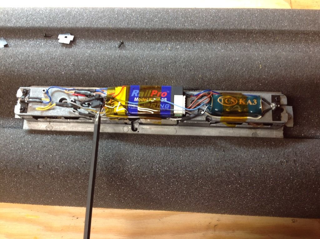
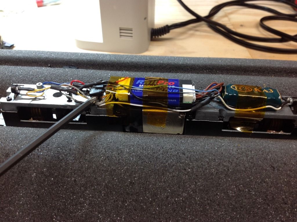
The screwdriver marks the location of the bridge rectifier:

Note the size of the bridge rectifier and the KA. This in a Bachmann RS3 for reference.

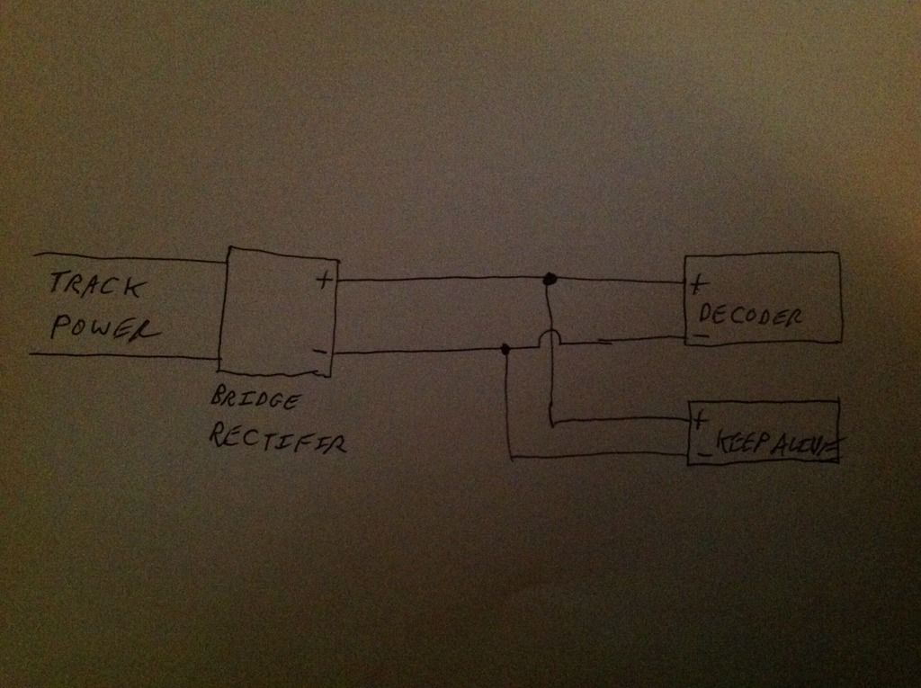
Schematic:

The bridge rectifier used here:
http://www.digikey.com/products/en?keywords=DF04SCTAt about 40 cents per rectifier, these seem to be a good option. I'll be ordering at least ten, as well some more tablet speakers for sound installs.
The only question I have, and I'll see if Rob has the answer, is did they just install the bridge rectifier on the red and black track power wires. I assume we just arbitrarily assign one of the wires to be positive and the other negative after the bridge rectifier....black for negative and red for positive for convenience. Am I correct in this assumption?