Author Topic: Keep Alive installation w/ Railpro  (Read 35915 times)

KPack

  • Conductor
  • ****
  • Posts: 770
Keep Alive installation w/ Railpro
« on: January 30, 2017, 10:05:58 AM »
This information is from Rob Cooper, a fellow Railpro user who had me install RP modules is most of his fleet.  The installs all went well, but the switchers would stall on yard ladders excessively.  Rob had a friend who is very familiar with electronics come and figure out how to install a TCS KeepAlive (KA).  At first they popped the cover on several modules and found two solder points on the internal bridge rectifier.  In the end they found it easier to install an external bridge rectifier.

Reports are that all stalling has ceased and locomotives run buttery smooth through all turnouts.

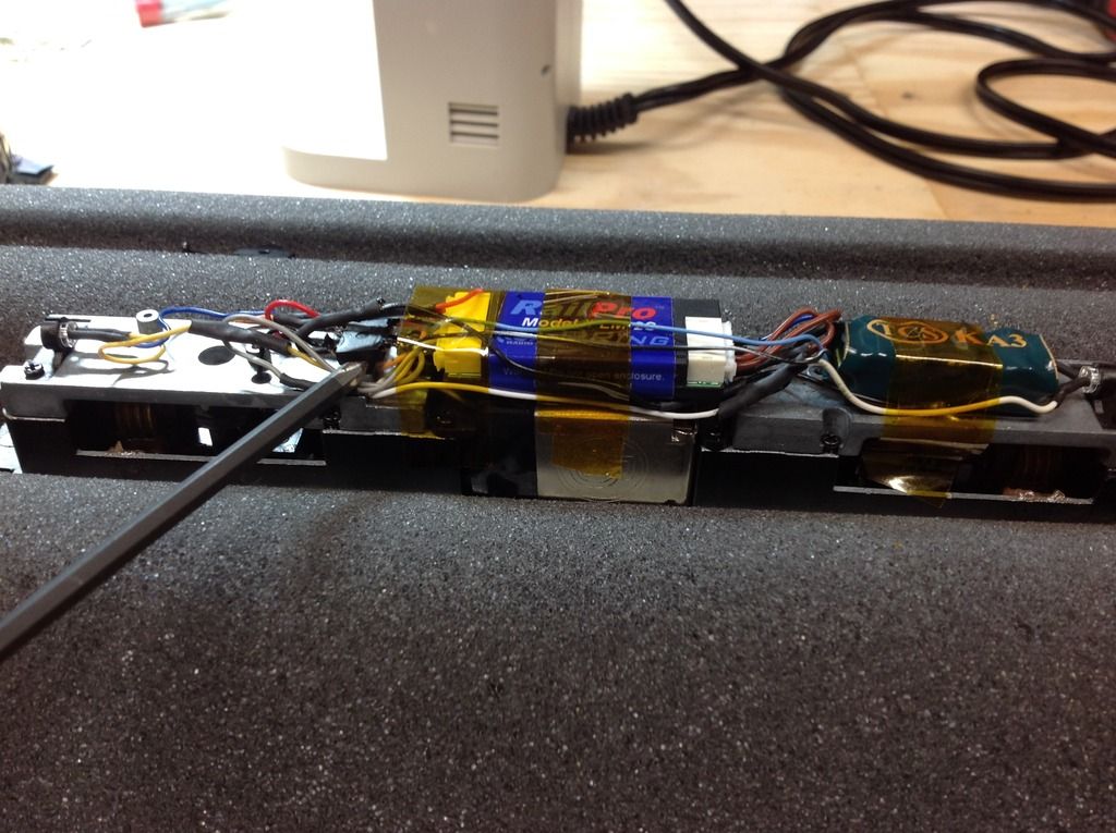
The screwdriver marks the location of the bridge rectifier:


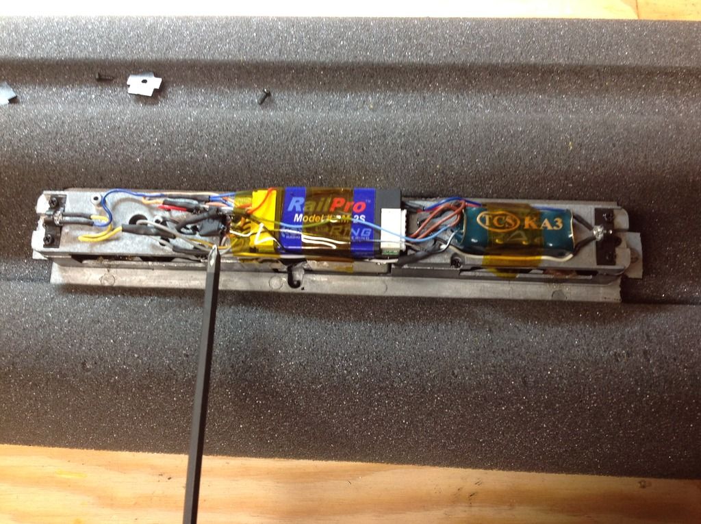
Note the size of the bridge rectifier and the KA.  This in a Bachmann RS3 for reference.
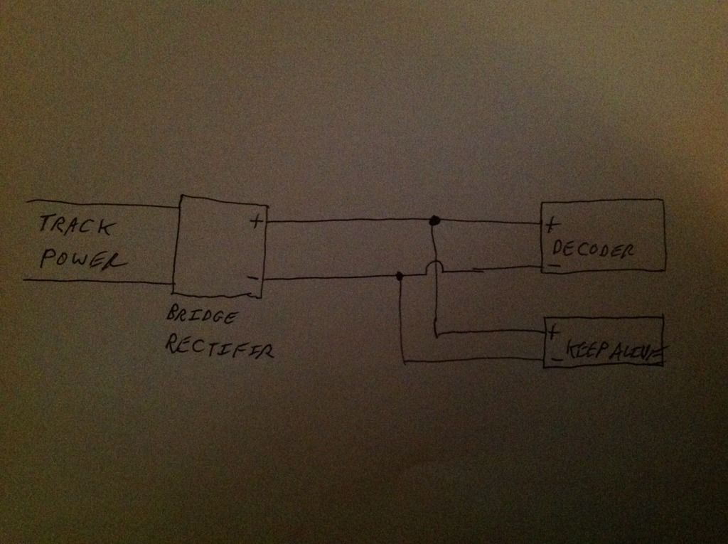

Schematic:


The bridge rectifier used here:
http://www.digikey.com/products/en?keywords=DF04SCT
At about 40 cents per rectifier, these seem to be a good option.  I'll be ordering at least ten, as well some more tablet speakers for sound installs.

The only question I have, and I'll see if Rob has the answer, is did they just install the bridge rectifier on the red and black track power wires.  I assume we just arbitrarily assign one of the wires to be positive and the other negative after the bridge rectifier....black for negative and red for positive for convenience.  Am I correct in this assumption?

SWA737

  • Engineer
  • ***
  • Posts: 61
Re: Keep Alive installation w/ Railpro
« Reply #1 on: January 30, 2017, 10:14:18 AM »
 It does not matter to the bridge rectifier which track wire comes to  which side of the rectifier. It reconciles if you will the polarity internally.  I just ordered 10 more keep alive circuits to continue converting my engine roster. Looking forward to having them all completed. If anyone is having issues with this, I highly recommend this ad on. It makes a huge difference
Rob

Alan

  • Conductor
  • ****
  • Posts: 1073
    • LK&O Railroad
Re: Keep Alive installation w/ Railpro
« Reply #2 on: January 30, 2017, 10:18:41 AM »
Track connection is arbitrary on the input side of a bridge rectifier as it is designed to accept an AC signal. The input leads will be labeled with an AC wave symbol. The output side of a bridge rectifier is polarized. Marked with + and -

eBay is great for buying these. $0.10 each or less if you don't mind a 30 day wait from China.

http://www.ebay.com/itm/10PCS-2W10-2A-Bridge-Diode-Rectifier-NEW-/401167556726?hash=item5d67732076:g:XEcAAOSwU-pXqO95
Alan

LK&O Railroad website

When I was a kid... no wait, I still do that. HO, 28x32, double deck, 1969, RailPro

SWA737

  • Engineer
  • ***
  • Posts: 61
Re: Keep Alive installation w/ Railpro
« Reply #3 on: January 30, 2017, 11:10:26 AM »
 You are correct Alan. The ones I have do have the sign waves on that side of the rectifier and  it does not matter which wire goes to which. Thanks, Rob

SWA737

  • Engineer
  • ***
  • Posts: 61
Re: Keep Alive installation w/ Railpro
« Reply #4 on: January 30, 2017, 11:12:22 AM »
 One question I do have and maybe you can answer it Allen? My track voltage is 14.4 V and when I measure the voltage coming off of the bridge rectifier, it is down to 12.5 V. Is that amount of voltage OK for the rail pro decoder?
Rob

Alan

  • Conductor
  • ****
  • Posts: 1073
    • LK&O Railroad
Re: Keep Alive installation w/ Railpro
« Reply #5 on: January 30, 2017, 11:15:40 AM »
Not that it really matters but be aware there is a 1.4V drop across a bridge rectifier. Assuming you are using the 14.8V RP power supply, your loco is now actually running on 13.4V. The HC1 throttle knob is not marked in volts so the motor voltage doesn't matter much in actual use. You just turn the knob a pinch more. However, the missing 1.4V will ever so slightly change the start and top speed of a loco. If you are picky about how your locos perform then some fine tuning of your RP start and max settings may be in order after installing a bridge rectifier.
Alan

LK&O Railroad website

When I was a kid... no wait, I still do that. HO, 28x32, double deck, 1969, RailPro

KPack

  • Conductor
  • ****
  • Posts: 770
Re: Keep Alive installation w/ Railpro
« Reply #6 on: January 30, 2017, 11:17:54 AM »
Sorry, I should clarify my question a bit.  I know that coming into the rectifier it doesn't matter what wire goes where, but coming out it is polarized.  My confusion had to do with TCS's wiring instructions, which say to attach the blue wire from the KA to the positive on the decoder, which in our case is the blue wire on the decoder.  I'm assuming the external bridge rectifier makes it so we can just hook the KA to the black and red power wires after the bridge rectifier going into the decoder?  As long as the +/- on the KA is the same as the polarity on the exit of the rectifier.  Am I making any sense?

-Kevin

Alan

  • Conductor
  • ****
  • Posts: 1073
    • LK&O Railroad
Re: Keep Alive installation w/ Railpro
« Reply #7 on: January 30, 2017, 11:24:37 AM »
Sorry Rob. I was posting while you were. By sheer accident almost answered your question. Sure, RP will run fine on 12.5V. Top speed may suffer.

A case could be made that if one loco has keep alive capacitors then all your locomotives should also. It would be interesting to study the MUing function between KA'ed and non-KA'ed. I am sure it will still work but am curious if there is an observable deterioration in function.
Alan

LK&O Railroad website

When I was a kid... no wait, I still do that. HO, 28x32, double deck, 1969, RailPro

Alan

  • Conductor
  • ****
  • Posts: 1073
    • LK&O Railroad
Re: Keep Alive installation w/ Railpro
« Reply #8 on: January 30, 2017, 11:41:04 AM »
Quote
As long as the +/- on the KA is the same as the polarity on the exit of the rectifier.

Correct.

The keep alive deal is nothing more than fundamental power supply smoothing. At the heart of virtually every power supply out there. Perhaps you have seen an illustration like this:

pwrsupsm.gif

The capacitor supplies current to fill in during the AC polarity changeover. This smooths the output voltage. The KA application functions the same except the periods of no supplied current (loss of connection to the track) are unpredictable in frequency or duration so a larger capacitor is needed to make sure there is sufficient current available to cover the longest interruption at maximum load. Electrolytic is a type of capacitor that can store a lot of energy in a small space. They are used in power supplies and KA for this reason. Electrolytic capacitors, with few odd exceptions, are polarized. Hence the + and - markings and why the KA has color coded wire leads. + must always be connected to + with an electrolytic capacitor. Hooked up backwards they explode. Sometimes violently.
Alan

LK&O Railroad website

When I was a kid... no wait, I still do that. HO, 28x32, double deck, 1969, RailPro

TwinStar

  • Conductor
  • ****
  • Posts: 512
  • Modeling a 1961 Rock Island Twin Star Rocket
Re: Keep Alive installation w/ Railpro
« Reply #9 on: January 30, 2017, 11:43:06 PM »
Fantastic!! I've been begging Tim for these for over a year now and I'm about to start wiring my E units for power and sound. This couldn't have come at a bette time. Hardware is being ordered now.

Thanks!
Jacob Damron
Modeling late 1950's Dallas Union Terminal in Free-mo+ modules

Texas Railway Modeling and Historical Society trmhs.org
trmhs.org

Dean

  • Conductor
  • ****
  • Posts: 211
Re: Keep Alive installation w/ Railpro
« Reply #10 on: February 02, 2017, 02:21:32 PM »
Seriously considering adding Keep Alive to my RailPro fleet. I understand how it works with DC, but what about DCC? You need a true RMS meter to measure the track voltage because of the DCC waveform. Will this affect the rectifier? Will the DCC signals being sent over the track have any affect?
Digitrax has a keep alive module that is much cheaper than the TCS module. Will it work using the same circuit?

Thanks   
Dean

Alan

  • Conductor
  • ****
  • Posts: 1073
    • LK&O Railroad
Re: Keep Alive installation w/ Railpro
« Reply #11 on: February 02, 2017, 04:11:20 PM »
Not being a user of either brand keep alive nor a DCC user, the best I can do is offer a bit of general information.

Keep alives use supercapacitors, sometimes called ultracapacitors, which are a type of super high density electrolytic capacitor. Large value capacitors, especially electrolytic, are slow changing devices on electrical timescales. They are sluggish. Because of this they do not smooth out high frequencies very well if at all. The DCC square wave is somewhere around 10kHz if I recall correctly. That may very well be above the effective frequency range of the capacitors used in these two commercial keep alive products.

Common in electrical circuits is a combination of a large capacitor and a small capacitor together to filter electrical noise on a supply line. The big slow capacitor supplies large current during the long dips while the little fast capacitor supplies current during the short quick dips. i.e. the big cap takes care of low frequencies, the little cap takes care of high frequencies. Here is a practical example used in my detection boards:

caps.png

In this circuit the 555 timer chip produces both low and high frequency noise on the supply line every time it changes state. Equate that to losing rail contact (low freq) and DCC signal (high freq). The big electrolytic on the board carries the load for the long slow changing dips. The little ceramic cap next to it reacts fast carrying the load during the short fast dips. The result is noise-free supply line. This big cap little cap combination is extensively used in electronics. If the little cap were not present then the the high frequency noise would still be on the supply line.  I suspect the keep alives work the same way.

« Last Edit: February 02, 2017, 05:15:42 PM by Alan »
Alan

LK&O Railroad website

When I was a kid... no wait, I still do that. HO, 28x32, double deck, 1969, RailPro

TwinStar

  • Conductor
  • ****
  • Posts: 512
  • Modeling a 1961 Rock Island Twin Star Rocket
Re: Keep Alive installation w/ Railpro
« Reply #12 on: February 03, 2017, 02:48:50 AM »
This setup will work whether you're applying DC or DCC to the rail, correct?
Jacob Damron
Modeling late 1950's Dallas Union Terminal in Free-mo+ modules

Texas Railway Modeling and Historical Society trmhs.org
trmhs.org

William Brillinger

  • Dispatcher (Admin)
  • Conductor
  • *****
  • Posts: 1324
    • Precision Design Co.
Re: Keep Alive installation w/ Railpro
« Reply #13 on: February 03, 2017, 07:41:04 AM »
Yes, this will wok with DC and DCC power.
- Bill Brillinger, RPUG Admin

Modeling the BNML in HO Scale, owner of Precision Design Co., and RailPro Dealer.


William Brillinger

  • Dispatcher (Admin)
  • Conductor
  • *****
  • Posts: 1324
    • Precision Design Co.
Re: Keep Alive installation w/ Railpro
« Reply #14 on: February 03, 2017, 07:41:32 AM »
Here is a nice overview of available Keep Alive options:

https://sites.google.com/site/markgurries/home/decoders/keep-alive-compatibility
- Bill Brillinger, RPUG Admin

Modeling the BNML in HO Scale, owner of Precision Design Co., and RailPro Dealer.