Author Topic: Stay Alive Circuitry  (Read 21931 times)

nodcc4me

  • Conductor
  • ****
  • Posts: 686
  • RailPro Fan
Re: Stay Alive Circuitry
« Reply #30 on: July 27, 2016, 07:26:15 PM »
I"m with Kevin.  :-\
Al

Run your train, not your brain. Get RailPro. It's a no-brainer.

Alan

  • Conductor
  • ****
  • Posts: 1073
    • LK&O Railroad
Re: Stay Alive Circuitry
« Reply #31 on: July 27, 2016, 09:17:35 PM »
Quote
Wouldn't the diode bridge prevent feedback of power from the capacitor to the rails anyway?

Answer

Could eliminate the resistor if not too many locos on the layout. Large amounts of capacitance may make it difficult or impossible to startup the power supply/breakers.

Sorry Bill. I totally misread your question. My eyes read diode. My brain heard resistor. You must be like Huh???

Yes, the diodes in the bridge rectifier do prevent the capacitor from discharging back to the power supply. So the bridge performs two functions - blocking and polarity rectification.
Alan

LK&O Railroad website

When I was a kid... no wait, I still do that. HO, 28x32, double deck, 1969, RailPro

William Brillinger

  • Dispatcher (Admin)
  • Conductor
  • *****
  • Posts: 1324
    • Precision Design Co.
Re: Stay Alive Circuitry
« Reply #32 on: July 27, 2016, 10:33:03 PM »
Phew. I thought I was losing it there.

So then for clarity: in light of the diode bridge, the resistor is not needed - correct?
- Bill Brillinger, RPUG Admin

Modeling the BNML in HO Scale, owner of Precision Design Co., and RailPro Dealer.


Alan

  • Conductor
  • ****
  • Posts: 1073
    • LK&O Railroad
Re: Stay Alive Circuitry
« Reply #33 on: July 28, 2016, 08:30:33 AM »
Quote
So then for clarity: in light of the diode bridge, the resistor is not needed - correct?

For a single loco on the layout the resistor is not needed. As more locos are added to the layout you will eventually reach a point where the combined inrush current of all the caps is so high that the power supply can't startup.

A cap is essentially a dead short at the instant of power up. It's resistance climbs very fast so the "short" is extremely brief. Power supplies are designed to allow excessive current to flow for a very brief moment during power up. If there are a lot of caps then the amount of time that excessive current must flow exceeds the power supply's ability to deliver. Hence, the power supply will shut down. This all happens so fast that it will appear the power supply refuses to turn on. Naturally higher output (amps) power supplies will turn on larger cap loads.

It should be noted that old style iron core transformer power supplies (below) don't suffer from this problem. They will start any cap load or send your wiring up in smoke trying!

Alan

LK&O Railroad website

When I was a kid... no wait, I still do that. HO, 28x32, double deck, 1969, RailPro

William Brillinger

  • Dispatcher (Admin)
  • Conductor
  • *****
  • Posts: 1324
    • Precision Design Co.
Re: Stay Alive Circuitry
« Reply #34 on: July 28, 2016, 08:44:38 AM »
Quote
For a single loco on the layout the resistor is not needed. As more locos are added to the layout you will eventually reach a point where the combined inrush current of all the caps is so high that the power supply can't startup.

Ah!  it all makes sense now.
- Bill Brillinger, RPUG Admin

Modeling the BNML in HO Scale, owner of Precision Design Co., and RailPro Dealer.


G8B4Life

  • Signalman (Global Mod)
  • Conductor
  • *****
  • Posts: 1192
  • I'll think of a catchy tag line one day
Re: Stay Alive Circuitry
« Reply #35 on: July 28, 2016, 10:06:56 AM »
Quote
Electrolytic capacitors experience RUD

I can attest to that. Way back in high school in electronics class, a fellow student decided to put a cap into a power point (240v) and turn it on. The resulting instant very loud explosion scared the daylights out of everyone and the student was lucky to still have his fingers intact; there was a large dint in the roof where part of the cap hit it.

Anyway this thread is proving most useful with quite a bit of knowledge to be picked up, especially on the dampening of the ringing. Alan, is there a reason why your component values (power dissipation I'm talking about) are so high for this? Back when I was almost a DCC user I did some reading on this and the component values given to do this for DCC wouldn't have handled that amount of power.

- Tim

Alan

  • Conductor
  • ****
  • Posts: 1073
    • LK&O Railroad
Re: Stay Alive Circuitry
« Reply #36 on: July 28, 2016, 01:23:21 PM »
Quote
Anyway this thread is proving most useful with quite a bit of knowledge to be picked up, especially on the dampening of the ringing. Alan, is there a reason why your component values (power dissipation I'm talking about) are so high for this? Back when I was almost a DCC user I did some reading on this and the component values given to do this for DCC wouldn't have handled that amount of power.

Because I am using a rude and crude method! :-[  And also because of the difference between DCC and RP DC.

Adding a parasitic load (100W resistors) is a crude way of fixing the problem because it is power wasteful - electricity turned into heat. But, it is the simplest to design, easiest to implement, and has the lowest initial cost. The penalty is a few additional cents on the electric bill!

Relative to DCC...   

DCC is an AC square wave on the rails. RP is steady state DC on the rails. This is an extremely important difference. AC buses react somewhat differently than DC buses when a load is applied or removed. While DCC also suffers from load change induced bus ringing, with RP the effect is more pronounced due to it being a DC system. On the flip side, DCC has to deal with all the waveform headaches while RP has no such issues.

Allan Gartner's Wiring for DCC site http://www.wiringfordcc.com/intro2dcc.htm explains the DCC waveform issues well. To borrow a couple of his images...

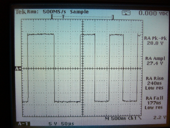
DCC waveform at the booster terminals:


DCC signal 25' from booster:
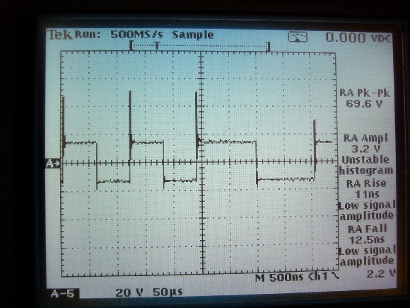


Closeup:


See the ringing in the DCC signal?

I found this trace online that, while not an actual DCC or RP measurement, is a close representation of what you might see if you put DCC and RP on the same scope. The green line = DCC, magenta line = RP. The DCC line rings on the leading and trailing edges of the square wave while the RP line rings when load is changed. Like I said, this is not an actual DCC RP scope trace but I'm hoping a picture is worth a thousand words.


It should be mentioned that none of this conversation applies to smaller layouts. Only large layouts, with long runs of wiring and power supplies (or DCC boosters) located large distances away, have to be concerned with ringing. Even then it doesn't seem to be an operational problem for RP, rather it is the fact Tim put that darn warning icon on the controller causing me to investigate further. It bothered me that I went to such trouble building a low voltage drop bus system and still got an occasional warning icon. Had to fix that.  >:( Obviously the fix is optional, not mandatory. All other RP layouts are doing fine without it. For my own sanity I had to silence the warning icon.     

Wattage-wise:
DCC layouts must accurately control the AC waveform shape in order to work correctly. Long wiring runs, parallel wire paths, and other model railroad realities play havoc on a square waveform. The various components, usually EMI filters and bus terminations, are [may be] added to a DCC track bus to better sharpen the square wave control signal that the layout wiring inductance is otherwise destroying. Minimizing the adverse effects of wiring on the waveform is the reason for many DCC best practices - keep booster distance to a minimum, twist the bus wires, etc. Shaping the AC waveform does not involve large current flow so high wattage components are not needed.

The components I added to my track bus are there to smooth a steady state DC line voltage. My crude method does this by placing a significant load on the line hence high wattage components. Adding new loads on the line (starting a loco) now represent less than 100% of the total current so they have less than 100% effect on the voltage regulation circuitry inside the power supply. Like driving a car with your feet on the brake pedal and accelerator at the same time.
Alan

LK&O Railroad website

When I was a kid... no wait, I still do that. HO, 28x32, double deck, 1969, RailPro

G8B4Life

  • Signalman (Global Mod)
  • Conductor
  • *****
  • Posts: 1192
  • I'll think of a catchy tag line one day
Re: Stay Alive Circuitry
« Reply #37 on: July 29, 2016, 12:03:46 AM »
Thanks Alan,

I had read Allan Gartner's site. Certainly a recommended site for those in to DCC.

So if I read you correctly, and in basic terms in DCC (AC) you need to "shape the waveform" with filters (resistor and capacitor usually) to dampen the ringing and in DC you need to "control the load" on the line (ballast resistor) to dampen the ringing?

I guess this might be one of the reasons Ring also makes a point about having short buses, "excessive heat generated by large resistors used for dampening at the end of a very long bus might cause a fire" ;)

This is actually good stuff to talk about as some might be contemplating long buses where ringing might become an issue. I know one of the major reasons for dampening the ringing in DCC is to assist in the prevention of the destruction of decoders (the voltage overshoot can and does kill decoders). I wonder if the same ringing issue could be a trap in waiting for us if one was not informed? Your trace back on page 2 showed a peak of about 25v, a significant amount above the max limit of 18v that Ring specifies. I'm sure that Ring has built some margin into it but I wonder?

- Tim

Alan

  • Conductor
  • ****
  • Posts: 1073
    • LK&O Railroad
Re: Stay Alive Circuitry
« Reply #38 on: July 29, 2016, 08:22:05 AM »
Quote
So if I read you correctly, and in basic terms in DCC (AC) you need to "shape the waveform" with filters (resistor and capacitor usually) to dampen the ringing and in DC you need to "control the load" on the line (ballast resistor) to dampen the ringing?

There are other methods but basically yes.

Quote
I guess this might be one of the reasons Ring also makes a point about having short buses, "excessive heat generated by large resistors used for dampening at the end of a very long bus might cause a fire" ;)

Voltage drop is a common primary concern with long buses as well. Ring may advise against long buses for multiple reasons. The resistors don't reach the ignition temperature of anything found on a model railroad so fire is unlikely but melting styrofoam certainly is possible.

Quote
I'm sure that Ring has built some margin into it but I wonder?

During my circuit breaker design and test process I exposed a LM2 to brutal conditions by repeatedly creating dead shorts on the rails with the loco at near stall current draw. I was dialing in my breaker design through trial and err. That one LM2 experienced several hundred shorts on a 15V 5A supply with no dampening whatsoever. It survived without damage and is operating inside a loco on the layout today. A DCC decoder would have checked out after the first couple shorts. LM2 is one tough cookie.
Alan

LK&O Railroad website

When I was a kid... no wait, I still do that. HO, 28x32, double deck, 1969, RailPro

Josephbw

  • Conductor
  • ****
  • Posts: 251
Re: Stay Alive Circuitry
« Reply #39 on: July 29, 2016, 08:53:05 AM »
"I guess this might be one of the reasons Ring also makes a point about having short buses, "excessive heat generated by large resistors used for dampening at the end of a very long bus might cause a fire" ;)"


So what would be considered a long bus run? I'm going to have a fairly large layout for a home, and will eventually have at least 2 power supplies, possibly 4.

Thanks for this discussion,
Joe

William Brillinger

  • Dispatcher (Admin)
  • Conductor
  • *****
  • Posts: 1324
    • Precision Design Co.
Re: Stay Alive Circuitry
« Reply #40 on: July 29, 2016, 09:26:57 AM »
My layout has 3 runs of almost 60ft on one PWR56 and I don't have any where that fails the coin test.
« Last Edit: July 29, 2016, 09:32:17 AM by William Brillinger »
- Bill Brillinger, RPUG Admin

Modeling the BNML in HO Scale, owner of Precision Design Co., and RailPro Dealer.


G8B4Life

  • Signalman (Global Mod)
  • Conductor
  • *****
  • Posts: 1192
  • I'll think of a catchy tag line one day
Re: Stay Alive Circuitry
« Reply #41 on: July 29, 2016, 09:35:43 AM »
Quote
Voltage drop is a common primary concern with long buses as well. Ring may advise against long buses for multiple reasons. The resistors don't reach the ignition temperature of anything found on a model railroad so fire is unlikely but melting styrofoam certainly is possible.

I know, I was having a bit of a poke of fun at Rings repeated deceleration of "it might cause a fire if it's not our product" in his manuals. I rekon big resistors that can generate a lot of heat would get this warning from Ring.

Voltage drop is the most probable reason for the "short" bus length that Ring advises as the PWR-56 can only take 16AWG wire. I do wish the PWR-56 had bigger terminals; 14 would be better and 12 even more so.

Joe, The PWR-56 manual give a bus length of 30 feet. That can translate into 60 feet (30 feet each way) if your supply is in the middle of the 60 feet but you'd need to make a splitter to do that. Alan might be able to give a better idea of the most practical length you could go to before ringing might become a problem that needs treatment.

- Tim

melarson

  • Guest
Re: Stay Alive Circuitry
« Reply #42 on: July 29, 2016, 11:45:14 AM »
Voltage drop is the most probable reason for the "short" bus length that Ring advises as the PWR-56 can only take 16AWG wire. I do wish the PWR-56 had bigger terminals; 14 would be better and 12 even more so.

I'm sure I'm not the first to think of this, but you can come out of the PWR-56 with a short length (1, 2, 3 inches, whatever you deem necessary) of 16AWG and then either solder it to your 12AWG bus or connect it to a conventional terminal block with your 12AWG bus on the other side.

BTW, if 30 feet is the recommended length for 16AWG, then simple math will show that your 12AWG bus can be approximately 2-1/2 times longer (right close to 76 feet) for the same voltage drop.  For large layouts this would seem very beneficial.

(Length of 12AWG bus derived from the ohms per thousand feet rating of both wire sizes.)

Alan

  • Conductor
  • ****
  • Posts: 1073
    • LK&O Railroad
Re: Stay Alive Circuitry
« Reply #43 on: July 29, 2016, 12:29:06 PM »
Quote
So what would be considered a long bus run?

That is the $64,000 question for which you will never receive a 100% reliable answer. There are too many variables for one answer to be the right answer everywhere everytime. However, rest assured everyone will ask it!  ;D

Because people will ask, manufacturers like Ring attempt to give a single answer that will work 99.99% of the time. That makes the answers very conservative. Look at Bill's situation for instance. Ring says 30' Bill has 60' without problems. Shucks, I have 150' and it works fine. Abiding by artificially low recommendations may place an unnecessary constraint on your construction or dramatically increase your cost. Throwing caution to the wind by totally disregarding electrical design is equally dangerous. At the end of the day, the physical arrangement of your layout space, your appetite for wiring, and your wallet will force certain electrical realities upon you. Fortunately, RP seems to be extremely forgiving. That is a good thing. (to the DCC guys we say neener-neener)

Rather than a single answer it may be better to simply use best practices and let the chips fall where they may in any one situation.

Before I go on I want to say this again - we are talking about large layouts. None of this matters a lick on a smaller railroad. For sake of argument only, let's say a large layout is one where the wire between the power supply and the track is longer than Ring's recommended 30'. And we are talking RP, not DCC.

This much we know for sure - our power systems are effectively this:

power rails.jpg

with L = wiring inductance
with R = wiring resistance
with C = wiring capacitance
with V = power supply voltage
with A = load on the circuit (train)
Our goal is to minimize L, R, and C while stabilizing V. Our trains dictate A.
We also know the load on the circuit will vary so it is given L & C will always be in flux.
We also know the voltage regulator in our power supply is >30' from the load so assume regulation will be poor at best. This means not only will L & C change constantly, so will short-time V relative to A.

See how complicated the "right answer" to your question quickly becomes?

Off the cuff shot at best practices:

  • (LRC) Use the shortest practical wiring length - route wires in most direct path.
  • (LRC) Use the shortest practical wiring length - power supply in middle of wire run instead of at the end.
  • (LRC) Use isolated multiple power supplies dispersed around the layout if practical.
  • (R) Use the shortest practical effective wiring length - if using one power supply position it electrically central to the layout.
  • (R) Use largest practical wire gauge - effective upper limit of 14-12ga as they are the largest readily available economical copper wire sizes.
  • (R) Use a lot of short feeders - short <12" small gauge 24-20 to every rail is bulletproof while not being obtrusive trackside.
  • (R) Use a feeder for every 3-6' of contiguous rail - refer to ohm's law and the rail resistance of your specific brand track.
  • (R) Make high reliability low resistance electrical connections throughout.
  • (LC) Avoid parallel wires - Twist bus wires a turn per 1-2'.
  • (C) Don't deliberately add capacitance - avoid twisting wires into candy cane tightness.
  • (L) Don't deliberately add inductance - avoid small circular wire bundles.
  • (C) Limit the charge time of keep alive circuits.
  • (V) Possibly add a ballast load at mid-point furthest from power supply - big honkin' resistors.  ;D
  • (V) Possibly use a power supply(s) with remote sensing.
  • (R) The rails are equally part of the power system equation - solder joiners.

The are no doubt many more. My head hurts.
« Last Edit: July 29, 2016, 12:34:37 PM by Alan »
Alan

LK&O Railroad website

When I was a kid... no wait, I still do that. HO, 28x32, double deck, 1969, RailPro

Josephbw

  • Conductor
  • ****
  • Posts: 251
Re: Stay Alive Circuitry
« Reply #44 on: July 29, 2016, 05:26:41 PM »
At this point, I probably only have about 100' of track laid with only 6 pairs of track feeders. I am using 12 ga bus wire w/18 ga feeder wire, and I make sure all my track joints are electrically sound. I can take voltage measurements anywhere on the layout and get the same reading.

I only have about 1/4 of the potential track laid, but it may be 2-5 years before I am ready for operating sessions.

So much fun, so little time.  ;D

Joe