Author Topic: RP Keep Alive Installation  (Read 6886 times)

emd_16645

  • Conductor
  • ****
  • Posts: 114
    • Somerset Junction, 1980
RP Keep Alive Installation
« on: October 03, 2018, 05:31:43 AM »
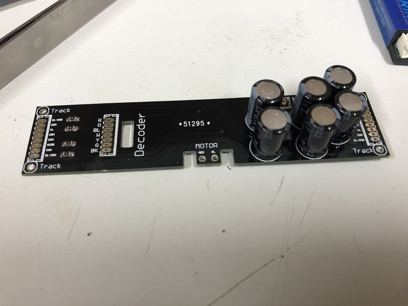
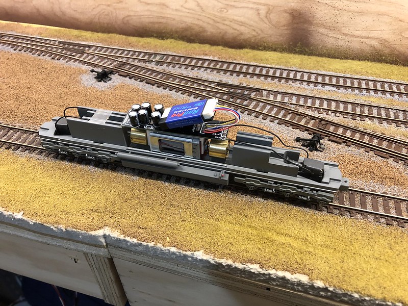
I'm working on installing a LM3S and a keep alive into a new to me early Genesis SD70M.  The keep alive I am using is integrated into a common electrical board that also handles lighting, etc, however the keep alive is electrically isolated on the board.  Last night I set the board up with a 9-pin plug, and installed into the loco drive, without setting up the keep alive function.  I set up the motor full load current, and got back a value in the 600 mA range (repeatable).  Seemed high, but everything functions, and I was able to run the loco back and forth several times. 

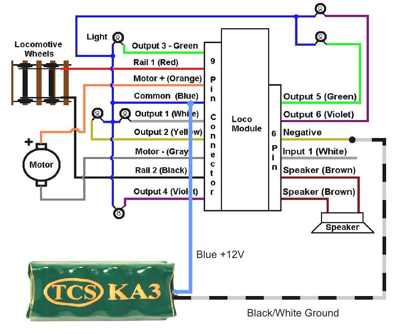
Next, I wired in the keep alive to the rest of the board.  I followed the diagram attached below.  I reran the motor full load current function, and got back 690 mA.  I also started having issues with the LM3 cutting out on high motor current (not surprising).  Also, I am not seeing an effect from the keep alive.  The track voltage did not stay stable, and fluctuated at known low points, and the motor immediately stopped when removed from the track.  Didn't get much farther due to being up late enough as it is.

So where I'm at with this.  First, being an early genesis model, I have low confidence in the quality of the motor.  I have not tried to wire in a different motor, and see how much of a difference it makes.  However, I'd expect that adding the keep alive should not affect motor current if it is working properly.  Any thoughts?

Board I am using.


Installed into drive.


Wiring diagram for keep alive I'm following.

Chris Bellows
Somerset Junction, 1980
somersetjunction.blogspot.com

G8B4Life

  • Signalman (Global Mod)
  • Conductor
  • *****
  • Posts: 1193
  • I'll think of a catchy tag line one day
Re: RP Keep Alive Installation
« Reply #1 on: October 03, 2018, 07:23:50 AM »
Very hard to see in the photo's as they don't link to any bigger versions, but I can't see a 6 pin harness in your second photo. Are you sure you didn't wire the KA part to the yellow wire on the 9 pin side instead of the yellow wire on the 6 pin side where it needs to be wired to?

- Tim


emd_16645

  • Conductor
  • ****
  • Posts: 114
    • Somerset Junction, 1980
Re: RP Keep Alive Installation
« Reply #2 on: October 03, 2018, 07:42:11 AM »
Tim,

The install photo was prior to installing the 6-pin.  The keep alive is wired to the fourth pin of the 6-pin plug (speaker wires occupying pins 1 and 2).  I can post another photo tonight showing it.
Chris Bellows
Somerset Junction, 1980
somersetjunction.blogspot.com

William Brillinger

  • Dispatcher (Admin)
  • Conductor
  • *****
  • Posts: 1326
    • Precision Design Co.
Re: RP Keep Alive Installation
« Reply #3 on: October 03, 2018, 07:55:08 AM »
What keep alive board is that?
- Bill Brillinger, RPUG Admin

Modeling the BNML in HO Scale, owner of Precision Design Co., and RailPro Dealer.


emd_16645

  • Conductor
  • ****
  • Posts: 114
    • Somerset Junction, 1980
Re: RP Keep Alive Installation
« Reply #4 on: October 03, 2018, 08:28:58 AM »
Came across it on the Canadian Modelers facebook group.  Made by a guy in BC by the name of Chris.  Runs a robotics electronics company apparently.  He mentioned making the board for DCC use, so I contacted him and determined that it should be useable for Railpro.  Board incorporates resistors for lighting to simplify LED installs.   
Chris Bellows
Somerset Junction, 1980
somersetjunction.blogspot.com

Alan

  • Conductor
  • ****
  • Posts: 1073
    • LK&O Railroad
Re: RP Keep Alive Installation
« Reply #5 on: October 03, 2018, 02:18:54 PM »
Something isn't right. The capacitors should draw current only for a brief moment while initially charging. That will be completed rapidly, well before your finger taps the settings button on your HC. So the fact they appear to be drawing 90mA during motor current test is a big red flag.

Does the board have a resistor and diode pair in series with the capacitors? This is a common arrangement to limit the maximum capacitor charging current. That could possibly explain the 90mA but seems unlikely. The 90mA number is still out of range of what would be expected. I do not see a resistor or diode on the board in your pics.

Aged (very aged) electrolytic capacitors sometimes develop DC current leakage across the internal dielectric. Is the board very old?

You can test the capacitors in isolation:
  • Disconnect the capacitors (board) from the LM and from the loco motor
  • Connect a 9V transistor battery to the capacitor leads for a few seconds making sure to observe proper polarity
  • Disconnect the battery
  • Connect a voltmeter or LED w/series resistor to the capacitor leads
If the capacitors are good the voltmeter should show 9 volts (or a little less) and very slowly drop voltage. Very, very slowly. If you used an LED it should glow for a long time, many minutes.
Alan

LK&O Railroad website

When I was a kid... no wait, I still do that. HO, 28x32, double deck, 1969, RailPro

emd_16645

  • Conductor
  • ****
  • Posts: 114
    • Somerset Junction, 1980
Re: RP Keep Alive Installation
« Reply #6 on: October 03, 2018, 03:04:17 PM »
Something isn't right. The capacitors should draw current only for a brief moment while initially charging. That will be completed rapidly, well before your finger taps the settings button on your HC. So the fact they appear to be drawing 90mA during motor current test is a big red flag.

Does the board have a resistor and diode pair in series with the capacitors? This is a common arrangement to limit the maximum capacitor charging current. That could possibly explain the 90mA but seems unlikely. The 90mA number is still out of range of what would be expected. I do not see a resistor or diode on the board in your pics.

Aged (very aged) electrolytic capacitors sometimes develop DC current leakage across the internal dielectric. Is the board very old?

You can test the capacitors in isolation:
  • Disconnect the capacitors (board) from the LM and from the loco motor
  • Connect a 9V transistor battery to the capacitor leads for a few seconds making sure to observe proper polarity
  • Disconnect the battery
  • Connect a voltmeter or LED w/series resistor to the capacitor leads
If the capacitors are good the voltmeter should show 9 volts (or a little less) and very slowly drop voltage. Very, very slowly. If you used an LED it should glow for a long time, many minutes.

Thanks for the input Alan. I have some testing to do. It will be a little harder, because everything is hardwired in. The board was assembled last week, I do not know the age of the capacitors but I can’t image they are that old. I believe there are resistors in line with the capacitors but I’m not sure.

Board with keep alive connected.
« Last Edit: October 03, 2018, 03:11:46 PM by emd_16645 »
Chris Bellows
Somerset Junction, 1980
somersetjunction.blogspot.com

emd_16645

  • Conductor
  • ****
  • Posts: 114
    • Somerset Junction, 1980
Re: RP Keep Alive Installation
« Reply #7 on: October 03, 2018, 03:14:18 PM »
I did some more testing this afternoon.  With the Max Speed set to about 70%, the motor stall current was 390 mA and the loco operated fairly smoothly.  Not sure how tied the speed setting is to the stall current is.  Keep alive does not seem to be functioning.  I will test the capacitors tonight.

Chris Bellows
Somerset Junction, 1980
somersetjunction.blogspot.com

TwinStar

  • Conductor
  • ****
  • Posts: 512
  • Modeling a 1961 Rock Island Twin Star Rocket
Re: RP Keep Alive Installation
« Reply #8 on: October 03, 2018, 05:18:13 PM »
Chris:

Kapton tape is recommend over the black tape. That is one of many things that I've learned here.

Good luck.


Jacob Damron
Modeling late 1950's Dallas Union Terminal in Free-mo+ modules

Texas Railway Modeling and Historical Society trmhs.org
trmhs.org

emd_16645

  • Conductor
  • ****
  • Posts: 114
    • Somerset Junction, 1980
Re: RP Keep Alive Installation
« Reply #9 on: October 03, 2018, 05:59:42 PM »
Chris:

Kapton tape is recommend over the black tape. That is one of many things that I've learned here.

Good luck.

Agreed, but it’s what I have on hand.  Bill was out of a stock the last time I ordered. Hopefully next time I buy from him he will have some.
Chris Bellows
Somerset Junction, 1980
somersetjunction.blogspot.com

William Brillinger

  • Dispatcher (Admin)
  • Conductor
  • *****
  • Posts: 1326
    • Precision Design Co.
Re: RP Keep Alive Installation
« Reply #10 on: October 03, 2018, 06:34:53 PM »
I have lots of kapton tape in stock now!
- Bill Brillinger, RPUG Admin

Modeling the BNML in HO Scale, owner of Precision Design Co., and RailPro Dealer.


Alan

  • Conductor
  • ****
  • Posts: 1073
    • LK&O Railroad
Re: RP Keep Alive Installation
« Reply #11 on: October 03, 2018, 06:57:47 PM »
Had another thought. It is possible the caps are not super caps, just plain ole caps. If that is the case, based on their size in the photo they may not have enough capacitance to run a 600mA load long enough to be noticeable.

What value are the caps? It will be marked on them. I can't see in your pics well enough to determine.
Alan

LK&O Railroad website

When I was a kid... no wait, I still do that. HO, 28x32, double deck, 1969, RailPro

emd_16645

  • Conductor
  • ****
  • Posts: 114
    • Somerset Junction, 1980
Re: RP Keep Alive Installation
« Reply #12 on: October 03, 2018, 08:47:46 PM »
Had another thought. It is possible the caps are not super caps, just plain ole caps. If that is the case, based on their size in the photo they may not have enough capacitance to run a 600mA load long enough to be noticeable.

What value are the caps? It will be marked on them. I can't see in your pics well enough to determine.

1F 2.7v.  Labeled 1802 PET if that means anything.
Chris Bellows
Somerset Junction, 1980
somersetjunction.blogspot.com

Alan

  • Conductor
  • ****
  • Posts: 1073
    • LK&O Railroad
Re: RP Keep Alive Installation
« Reply #13 on: October 03, 2018, 09:35:35 PM »
1F is a super cap. Since they are 2.7V then they must be wired series to work in a 15V circuit (2.7 x 6 = 16.2). Six 1F caps in series = 0.166F or 166,660µF which is a lot of capacitance.
series caps.PNG

If we assume the supply voltage is 14.8V and the LM will turn off when the voltage drops to 10V and the motor has 24.6Ω resistance ( 14.8V / .600mA = 24.6Ω ) then 166,660µF should provide 1.6 seconds of full load operation. This is ideal world calculation. Realistically you should expect about 1 - 1.5 second of operation.

drain.PNG

At this point the only logical conclusion is a fault in the wiring - incorrectly connected, cold solder joint, broken wire or board trace, etc. If you place a voltmeter on the capacitor leads while the loco is on powered track (0% throttle) what reading do you get? System voltage? What reading do you get if you turn off the track power? System voltage that slowly falls away? Same two scenarios and questions with the voltmeter connected to the LM common (blue on 9) and negative (yellow on 6) leads?
Alan

LK&O Railroad website

When I was a kid... no wait, I still do that. HO, 28x32, double deck, 1969, RailPro

emd_16645

  • Conductor
  • ****
  • Posts: 114
    • Somerset Junction, 1980
Re: RP Keep Alive Installation
« Reply #14 on: October 04, 2018, 05:01:34 AM »
Alan,

Supply voltage is 13.6 VAC (DCC powered layout)

I am getting 13.5 VDC across the LM3. When track power is removed it drops to 1.69v rapidly (within a second) and holds.

Across the cap bank I’m getting anywhere between 2.4v and 11v at normal state, with no apprarent consistency. Voltage drops off immediately if track power is removed. Looks like I need to get into contact with the manufacturer.
Chris Bellows
Somerset Junction, 1980
somersetjunction.blogspot.com