Author Topic: ScaleTrains LM-3S Question  (Read 17348 times)

Smoke

  • Fireman
  • **
  • Posts: 34
ScaleTrains LM-3S Question
« on: May 12, 2020, 10:45:04 PM »
With all of the lights that ScaleTrains now includes on the locomotives I have a question for how to wire it to a LM-3S/LM-3.

With the 6 light outputs of the LM, I am not sure how to keep all lighting functions:

Output 1: Front Headlights & numberboards
Output 2 & 3: Front ditch lights
Output 4 Rear Headlights & numberboards
Output 5 & 6: Rear Ditch lights

How would I light the step and walkway lights? Based on the other Scaletrains installs I've seen, I know I can connect all the step/walkway lights to one output ( I just don't know what output they would go to).

Other ST Installs for reference:
https://rpug.pdc.ca/index.php/topic,954.msg7319.html#msg7319
https://rpug.pdc.ca/index.php/topic,961.msg7332.html#msg7332
-Andrew

Smoke

  • Fireman
  • **
  • Posts: 34
Re: ScaleTrains LM-3S Question
« Reply #1 on: May 13, 2020, 08:49:08 AM »
After thinking about it more, I realized the previous installations don't have rear ditch lights. This allows for those two outputs (or one) to be used for the step/walkway lights.

Is there a clever way to add another output, or am I stuck wiring the step/walkway lights to track power at this point? I'm wondering if there is a way electrically to make it so if I turn a function on/off/on (within a span of 3 seconds) that I could trigger another output (I know how to do it in software, but I can't fit an Arduino inside the loco). Flip flops and a 555 come to mind for this, but I don't have a ton of experience with either of these to know if they would work as intended.
« Last Edit: May 13, 2020, 08:53:44 AM by Smoke »
-Andrew

G8B4Life

  • Signalman (Global Mod)
  • Conductor
  • *****
  • Posts: 1252
  • I'll think of a catchy tag line one day
Re: ScaleTrains LM-3S Question
« Reply #2 on: May 13, 2020, 09:31:08 AM »
If you don't need the ditch lights to flash that'll save you two outputs. You can't magically create any extra output's from the LM but your second query gave me an idea to create one out of thin air . You'd probably have to make a little circuit board to do this, and with limited space in loco's these days...

Presuming you have ditch lights front and back you could wire just one / one pair of outputs to a circuit that, with a little bit of circuit magic, having either the front or rear headlight output's on determines if the front or rear ditch lights are used. Figuring that if you were going forward you wouldn't flash the rear ditch lights would you? To make it even easier you could have that circuit be a simple relay type circuit, ie, rear headlight on = relay energised = rear ditch lights otherwise relay off = default front ditch lights. That is so ultra simple I'm probably overlooking something! Of course a relay and associated components would be too big but something like an opto-coupler (or is that opto-isolator)?

Edit: An added bonus of doing it this way is that if your prototype has the ditch lights flash when the horn is used then both the front and rear ditch lights will flash appropriately when you use the Auto ditch lights on horn setting in the LM. I think the LM's are still non directional in that regard and only auto flash the first set of ditch light configured in the LM.

- Tim
« Last Edit: May 13, 2020, 09:42:33 AM by G8B4Life »

Smoke

  • Fireman
  • **
  • Posts: 34
Re: ScaleTrains LM-3S Question
« Reply #3 on: May 13, 2020, 10:48:17 PM »
Tim, I was hoping against all odds you could magically add an output to the LM, but I knew my chances were less than winning the lottery!  ;D

The wiring should be fairly simple as you mentioned, check which headlight is on and the corresponding ditch light pair should be lit. The way I have it shown below the front headlights would have to be on for the front ditch lights to be on, whereas the rear ditch lights could be turned on without the rear headlight being on. Not a big deal as the headlights should always be on with the ditch lights.

Now to see if I can find a small package relay that will work.


« Last Edit: May 13, 2020, 10:58:05 PM by Smoke »
-Andrew

G8B4Life

  • Signalman (Global Mod)
  • Conductor
  • *****
  • Posts: 1252
  • I'll think of a catchy tag line one day
Re: ScaleTrains LM-3S Question
« Reply #4 on: May 14, 2020, 05:10:36 AM »
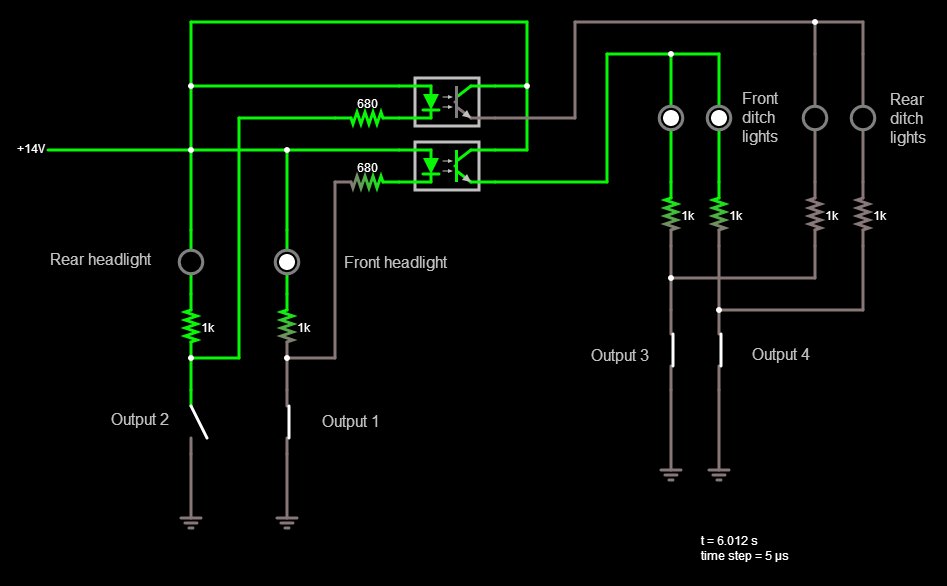
This might work better, and be smaller than a relay too.
ditch light idea v2.png
Click to make bigger

A pair of SMD opto isolators (can someone please explain the difference between an opto coupler and opto isolator in laymans terms!) and their resistors make up the device. You'd have to research the opto isolators to use as you'd want at least 50mA on the output channel, even though in the drawing as it is the ditch lights only "flow" about 20mA in total anyway.

You could also make you own opto isolator like this too, but that'd need research as well.


With this version the ditch lights are still dependent on the headlight being on but you can have both front and rear ditch lights on, and of course the Auto flash ditch lights on horn function works for both front and rear ditch lights. The only thing I'm not sure about is how dimming the headlight will affect the opto isolator.

Now, Alan will hopefully come along and tell me where my mistake is because there's bound to be one, even though the simulator says it works.

I can't post the url because it's over 2000 characters long but you can import the attached text file into Paul Falstads circuit simulator to run the simulation.

*ditch light idea v2.txt

- Tim

Alan

  • Conductor
  • ****
  • Posts: 1073
    • LK&O Railroad
Re: ScaleTrains LM-3S Question
« Reply #5 on: May 14, 2020, 10:04:30 AM »
Tim, your circuit looks fine to me. You don't give yourself enough credit.

Optocouplers use light from a LED to saturate (turn on) a phototransistor. Optoisolators use radio waves from a transmitter to trigger a receiver which in turn saturates a transistor. Their fundamental purpose is the same - join together two circuits without using an electrical connection. Optoisolators use CMOS technology so they are less expensive, more reliable, and operate at much lower power. However, due to the use of CMOS construction optoisolators are static sensitive so stick with optocouplers for model train uses. Here is a whitepaper if you want to delve into the detail: https://www.mouser.com/pdfDocs/siliconlabswhitepaper_isolator_vs_optocoupler_technology_updated.pdf
Alan

LK&O Railroad website

When I was a kid... no wait, I still do that. HO, 28x32, double deck, 1969, RailPro

G8B4Life

  • Signalman (Global Mod)
  • Conductor
  • *****
  • Posts: 1252
  • I'll think of a catchy tag line one day
Re: ScaleTrains LM-3S Question
« Reply #6 on: May 14, 2020, 11:05:02 AM »
Well thanks Alan, but there's not a whole lot of credit to give myself on this one, I just played around in the simulator for hours (lots of fun actually) until I made something that worked for what was needed and then refined it (the first version had a big no-no until I remembered not to do something a particular way).  I expected there to be a mistake as just because the simulator said it worked doesn't mean that it would, and I got so thoroughly confused trying to understand the datasheet for an opto coupler that I didn't really know if it should be used in the way I've done it, even though the simulator said it would work.

Also, thank you for the very clear and concise simple explanation of the difference between an opto coupler and opto isolator. Why can't electronics sites have the same clear, concise, simple explanations as you?  :)

Oh, for Smoke I should have pointed out in my circuit diagram post that the resistors for the opto couplers will need to be sized for the opto couplers that one picks.

This is the one I based my diagram off: https://www.digikey.com/product-detail/en/broadcom-limited/HCPL-181-00BE/516-1787-1-ND/1966493.

- Tim

Smoke

  • Fireman
  • **
  • Posts: 34
Re: ScaleTrains LM-3S Question
« Reply #7 on: May 14, 2020, 11:40:20 AM »
The circuit creater/tester is really cool!

I'm a little confused how I would actually wire the circuit you've drawn. You have the switched outputs being common, with a constant 14VDC supply. I was under the impression that the outputs were positive and common would be negative, but you have it drawn the opposite way. Are the outputs actually switched ground?
-Andrew

G8B4Life

  • Signalman (Global Mod)
  • Conductor
  • *****
  • Posts: 1252
  • I'll think of a catchy tag line one day
Re: ScaleTrains LM-3S Question
« Reply #8 on: May 14, 2020, 12:12:27 PM »
Yes, Paul Falstads circuit simulator is really cool.

Yep, RP outputs are switched ground, so in my diagram the +14v is the LM blue wire (common) and output 1 is the is the white wire (9 pin side), output 2 is the yellow wire (9 pin side), output 3 the green wire (9 pin side) and so on (http://ringengineering.com/RailPro/Documents/LM-3Instructions.pdf). I've draw in "switches" in the diagram to simulate turning the functions on/off.

Hopefully what I've written allows you to follow the diagram, I can't explain it any better at this time of the morning. I need rest.

- Tim

Alan

  • Conductor
  • ****
  • Posts: 1073
    • LK&O Railroad
Re: ScaleTrains LM-3S Question
« Reply #9 on: May 14, 2020, 01:34:19 PM »
The circuit creater/tester is really cool!

I'm a little confused how I would actually wire the circuit you've drawn. You have the switched outputs being common, with a constant 14VDC supply. I was under the impression that the outputs were positive and common would be negative, but you have it drawn the opposite way. Are the outputs actually switched ground?

RP modules, along with most electronics, use a transistor to ground as the switch. This is referred to as "sinking" current as opposed to having the switch on the high side (+ v) which is called "sourcing" current. The reason for sinking current being the popular approach has to do with a transistor's physical construction. NPN material transistors sink current. PNP material transistors source current. PNP material must have ≈3x surface area of NPN material for equivalent current carrying capability. This is due to the physics of electron/hole mobility inside the semiconductor wafer material itself. NPNs are therefore less expensive to make, take up less space, and switch on/off faster. Under the hood we live in a NPN dominated world.
Alan

LK&O Railroad website

When I was a kid... no wait, I still do that. HO, 28x32, double deck, 1969, RailPro

Smoke

  • Fireman
  • **
  • Posts: 34
Re: ScaleTrains LM-3S Question
« Reply #10 on: May 14, 2020, 06:39:03 PM »
Yes, Paul Falstads circuit simulator is really cool.

Yep, RP outputs are switched ground, so in my diagram the +14v is the LM blue wire (common) and output 1 is the is the white wire (9 pin side), output 2 is the yellow wire (9 pin side), output 3 the green wire (9 pin side) and so on (http://ringengineering.com/RailPro/Documents/LM-3Instructions.pdf). I've draw in "switches" in the diagram to simulate turning the functions on/off.

Hopefully what I've written allows you to follow the diagram, I can't explain it any better at this time of the morning. I need rest.

- Tim


It makes perfect sense knowing the LM is used switched ground. I will see if I can find a dual channel optocoupler to design around, otherwise I will plan on using 2 single channel ones.

The circuit creater/tester is really cool!

I'm a little confused how I would actually wire the circuit you've drawn. You have the switched outputs being common, with a constant 14VDC supply. I was under the impression that the outputs were positive and common would be negative, but you have it drawn the opposite way. Are the outputs actually switched ground?

RP modules, along with most electronics, use a transistor to ground as the switch. This is referred to as "sinking" current as opposed to having the switch on the high side (+ v) which is called "sourcing" current. The reason for sinking current being the popular approach has to do with a transistor's physical construction. NPN material transistors sink current. PNP material transistors source current. PNP material must have ≈3x surface area of NPN material for equivalent current carrying capability. This is due to the physics of electron/hole mobility inside the semiconductor wafer material itself. NPNs are therefore less expensive to make, take up less space, and switch on/off faster. Under the hood we live in a NPN dominated world.

Thanks for the info Alan. I've dealt with sinking and sourcing before (mostly with DI/O), but never had a clear understanding of what they actually were. Now the concept makes sense on why you would use sinking instead of sourcing.


-Andrew

Alan

  • Conductor
  • ****
  • Posts: 1073
    • LK&O Railroad
Re: ScaleTrains LM-3S Question
« Reply #11 on: May 14, 2020, 07:15:19 PM »
MCT6 is a widely available, low cost, general purpose optocoupler available in SMD or through hole. About $0.50 ea.

http://www.vishay.com/docs/83645/mct6.pdf
Alan

LK&O Railroad website

When I was a kid... no wait, I still do that. HO, 28x32, double deck, 1969, RailPro

Smoke

  • Fireman
  • **
  • Posts: 34
Re: ScaleTrains LM-3S Question
« Reply #12 on: May 15, 2020, 08:53:44 AM »
Thanks Alan! I sent you a PM with some questions for designing the PCB.
« Last Edit: May 15, 2020, 09:15:06 AM by Smoke »
-Andrew