Anyway this thread is proving most useful with quite a bit of knowledge to be picked up, especially on the dampening of the ringing. Alan, is there a reason why your component values (power dissipation I'm talking about) are so high for this? Back when I was almost a DCC user I did some reading on this and the component values given to do this for DCC wouldn't have handled that amount of power.
Because I am using a rude and crude method!

And also because of the difference between DCC and RP DC.
Adding a parasitic load (100W resistors) is a crude way of fixing the problem because it is power wasteful - electricity turned into heat. But, it is the simplest to design, easiest to implement, and has the lowest initial cost. The penalty is a few additional cents on the electric bill!
Relative to DCC...
DCC is an AC square wave on the rails. RP is steady state DC on the rails. This is an extremely important difference. AC buses react somewhat differently than DC buses when a load is applied or removed. While DCC also suffers from load change induced bus ringing, with RP the effect is more pronounced due to it being a DC system. On the flip side, DCC has to deal with all the waveform headaches while RP has no such issues.
Allan Gartner's Wiring for DCC site
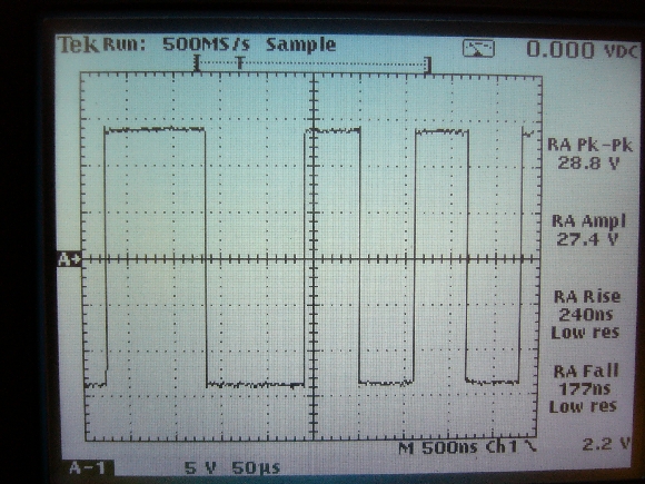
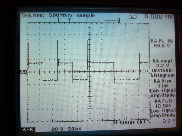
http://www.wiringfordcc.com/intro2dcc.htm explains the DCC waveform issues well. To borrow a couple of his images...
DCC waveform at the booster terminals:

DCC signal 25' from booster:

Closeup:

See the ringing in the DCC signal?
I found this trace online that, while not an actual DCC or RP measurement, is a close representation of what you might see if you put DCC and RP on the same scope. The green line = DCC, magenta line = RP. The DCC line rings on the leading and trailing edges of the square wave while the RP line rings when load is changed. Like I said, this is not an actual DCC RP scope trace but I'm hoping a picture is worth a thousand words.

It should be mentioned that none of this conversation applies to smaller layouts. Only large layouts, with long runs of wiring and power supplies (or DCC boosters) located large distances away, have to be concerned with ringing. Even then it doesn't seem to be an operational problem for RP, rather it is the fact Tim put that darn warning icon on the controller causing me to investigate further. It bothered me that I went to such trouble building a low voltage drop bus system and still got an occasional warning icon. Had to fix that.

Obviously the fix is optional, not mandatory. All other RP layouts are doing fine without it. For my own sanity I had to silence the warning icon.
Wattage-wise:
DCC layouts must accurately control the AC waveform shape in order to work correctly. Long wiring runs, parallel wire paths, and other model railroad realities play havoc on a square waveform. The various components, usually EMI filters and bus terminations, are [may be] added to a DCC track bus to better sharpen the square wave control signal that the layout wiring inductance is otherwise destroying. Minimizing the adverse effects of wiring on the waveform is the reason for many DCC best practices - keep booster distance to a minimum, twist the bus wires, etc. Shaping the AC waveform does not involve large current flow so high wattage components are not needed.
The components I added to my track bus are there to smooth a steady state DC line voltage. My crude method does this by placing a significant load on the line hence high wattage components. Adding new loads on the line (starting a loco) now represent less than 100% of the total current so they have less than 100% effect on the voltage regulation circuitry inside the power supply. Like driving a car with your feet on the brake pedal and accelerator at the same time.