Author Topic: Dual Switch Single Track Wiring  (Read 7372 times)

TwinStar

  • Conductor
  • ****
  • Posts: 512
  • Modeling a 1961 Rock Island Twin Star Rocket
Dual Switch Single Track Wiring
« on: January 03, 2019, 07:06:23 PM »
My Dallas Union Terminal module set is coming along nicely and I'm preparing to lay the six tracks that will serve the platforms. Free-mo setups typically devolve into a 'six tracks six trains' mentality. As such I don't want to have to listen to 18 sound equipped locos spewing out sounds non-stop. I want to install 'kill' switches that will silence a train as it waits for 'passengers to disembark and embark'.

Each track will be gapped and isolated. Each track needs two switches, one on each side of the module, and I would like for the switches (I don't really care about style) to be illuminated on when the track is live. Some of the lights in my house work with a similar setup so I know the concept is doable but I just don't know how to do it.

Any input on wiring or hardware would be much appreciated.
Jacob Damron
Modeling late 1950's Dallas Union Terminal in Free-mo+ modules

Texas Railway Modeling and Historical Society trmhs.org
trmhs.org

G8B4Life

  • Signalman (Global Mod)
  • Conductor
  • *****
  • Posts: 1192
  • I'll think of a catchy tag line one day
Re: Dual Switch Single Track Wiring
« Reply #1 on: January 03, 2019, 09:03:03 PM »
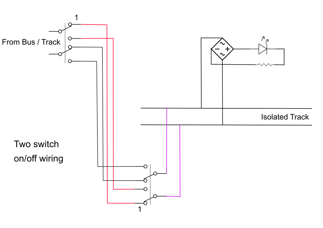
This is the same way as the light in your house (the isolated track being the light bulb) and uses two DPDT toggle switches as you want to switch both rails not just one as in the house wiring.

I don't think having the switches themselves light up is doable for most switches, you'd need a switch with separate light inputs (most just light up from the power they are switching) in which case you'd simply extend the bridge/LED (only one shown, you'd want one for each side of the module) to the switch instead of the fascia.

The bridge rectifier is of course required for when DCC is powering the tracks.

While this way is simple all that wiring might be tedious. I wonder of Alan could come up with a simple but way cool push on/push off system that works from both sides of the module?

two_switch_on_off.png


- Tim


Alan

  • Conductor
  • ****
  • Posts: 1073
    • LK&O Railroad
Re: Dual Switch Single Track Wiring
« Reply #2 on: January 03, 2019, 10:17:24 PM »
If only two switch locations are needed then Tim's suggestion seems the most practical. Jacketed 4 conductor phone cable would work well. If desired, you could eliminate the bridge rectifier(s) by simply using two LEDs wired anti-parallel with one LED painted over so you don't see it light.

If in a similar situation you require many switch locations then it would make more sense to control a track power relay with a flip flop circuit such as this one found on Bill Bouden's site http://www.bowdenshobbycircuits.info/page9.htm#4013.gif. With this circuit controlling the relay you could use as many momentary push buttons as you wish all connected with a single small gauge wire pair. The schematic makes it look far more complicated than it really is. All parts are super common dirt cheap components and could easily be made on a little 2" x 2" breadboard for $5 or so.

4013.gif
Alan

LK&O Railroad website

When I was a kid... no wait, I still do that. HO, 28x32, double deck, 1969, RailPro

TwinStar

  • Conductor
  • ****
  • Posts: 512
  • Modeling a 1961 Rock Island Twin Star Rocket
Re: Dual Switch Single Track Wiring
« Reply #3 on: January 07, 2019, 10:30:12 PM »
Tim and Alan:

Thank you both. I'm undecided where I want my kill switches. The Union Station tracks approach 20' and I'm trying to decide if I want kill switches located in the center of each side of if I want kill switches on each end of each side (4 then in this case).

Alan, is that schematic something that I'd have to build?
Jacob Damron
Modeling late 1950's Dallas Union Terminal in Free-mo+ modules

Texas Railway Modeling and Historical Society trmhs.org
trmhs.org


TwinStar

  • Conductor
  • ****
  • Posts: 512
  • Modeling a 1961 Rock Island Twin Star Rocket
Jacob Damron
Modeling late 1950's Dallas Union Terminal in Free-mo+ modules

Texas Railway Modeling and Historical Society trmhs.org
trmhs.org

Alan

  • Conductor
  • ****
  • Posts: 1073
    • LK&O Railroad
Re: Dual Switch Single Track Wiring
« Reply #6 on: January 13, 2019, 12:34:35 PM »
Is this the entirety of what I need save for wire and switches? I'd assume a 12V+/- input for power, multiple wire pairs from each switch, and then a singe or dual in/out for one or both track feeders?

Yep. You have it all correct. China just made life real easy for you.
Alan

LK&O Railroad website

When I was a kid... no wait, I still do that. HO, 28x32, double deck, 1969, RailPro

TwinStar

  • Conductor
  • ****
  • Posts: 512
  • Modeling a 1961 Rock Island Twin Star Rocket
Re: Dual Switch Single Track Wiring
« Reply #7 on: January 13, 2019, 02:17:05 PM »
Is this the entirety of what I need save for wire and switches? I'd assume a 12V+/- input for power, multiple wire pairs from each switch, and then a singe or dual in/out for one or both track feeders?

Yep. You have it all correct. China just made life real easy for you.

Awesome. Now more stupid questions if I may.

Will these open/close the circuit on both rails or just one?

I assume I need momentary style switches? SPST?

I also assume an LED wired in parallel with the track circuit would indicate track status?

Thanks so much.
Jacob Damron
Modeling late 1950's Dallas Union Terminal in Free-mo+ modules

Texas Railway Modeling and Historical Society trmhs.org
trmhs.org

Alan

  • Conductor
  • ****
  • Posts: 1073
    • LK&O Railroad
Re: Dual Switch Single Track Wiring
« Reply #8 on: January 13, 2019, 02:36:06 PM »
The relay supplied on the board is SPDT so it will switch on/off only one rail. You would need a DPST or DPDT relay to switch both rails. Why do you need to switch both rails? An open circuit is an open circuit regardless of how many opens there are in it.

Yes, momentary contact switches. SPST

Yes, LED wired in parallel with track. Don't forget the current limiting resistor. If the track will ever see DCC power then you should also wire a regular diode in series with the LED to prevent damaging the LED when the DCC power is on the negative pulses. A regular diode will add an additional 0.7V drop so remember to include in your limiting resistor calculation.
Alan

LK&O Railroad website

When I was a kid... no wait, I still do that. HO, 28x32, double deck, 1969, RailPro

TwinStar

  • Conductor
  • ****
  • Posts: 512
  • Modeling a 1961 Rock Island Twin Star Rocket
Re: Dual Switch Single Track Wiring
« Reply #9 on: January 13, 2019, 04:24:07 PM »
The relay supplied on the board is SPDT so it will switch on/off only one rail. You would need a DPST or DPDT relay to switch both rails. Why do you need to switch both rails? An open circuit is an open circuit regardless of how many opens there are in it.

Yes, momentary contact switches. SPST

Yes, LED wired in parallel with track. Don't forget the current limiting resistor. If the track will ever see DCC power then you should also wire a regular diode in series with the LED to prevent damaging the LED when the DCC power is on the negative pulses. A regular diode will add an additional 0.7V drop so remember to include in your limiting resistor calculation.

Alan, I was planning on only opening one rail to cut power but I thought someone had posted a need to open both. Thanks for affirming my original plan.

I'll get on Digikey and find some cool ones.

It will see both DCC and DC. I'm sure I'll be back confirming my resistor calculation!

Thanks again, I really appreciate the info.

Jacob Damron
Modeling late 1950's Dallas Union Terminal in Free-mo+ modules

Texas Railway Modeling and Historical Society trmhs.org
trmhs.org

TwinStar

  • Conductor
  • ****
  • Posts: 512
  • Modeling a 1961 Rock Island Twin Star Rocket
Re: Dual Switch Single Track Wiring
« Reply #10 on: January 13, 2019, 06:22:04 PM »
Just to make sure I'm in the right neighborhood...

Something like this?

SPST-NO circuit with an OFF-MOM function?

https://www.digikey.com/product-detail/en/e-switch/RP3502ABLK/EG1900-ND/280446
Jacob Damron
Modeling late 1950's Dallas Union Terminal in Free-mo+ modules

Texas Railway Modeling and Historical Society trmhs.org
trmhs.org

Alan

  • Conductor
  • ****
  • Posts: 1073
    • LK&O Railroad
Re: Dual Switch Single Track Wiring
« Reply #11 on: January 13, 2019, 06:58:29 PM »
Yep
Alan

LK&O Railroad website

When I was a kid... no wait, I still do that. HO, 28x32, double deck, 1969, RailPro

TwinStar

  • Conductor
  • ****
  • Posts: 512
  • Modeling a 1961 Rock Island Twin Star Rocket
Re: Dual Switch Single Track Wiring
« Reply #12 on: January 13, 2019, 07:30:36 PM »
Jacob Damron
Modeling late 1950's Dallas Union Terminal in Free-mo+ modules

Texas Railway Modeling and Historical Society trmhs.org
trmhs.org

Alan

  • Conductor
  • ****
  • Posts: 1073
    • LK&O Railroad
Re: Dual Switch Single Track Wiring
« Reply #13 on: January 13, 2019, 09:04:45 PM »
Had a few thoughts...

  • Connect the track to the NC side of the relay. That way you don't lose the track if something goes wrong with the China circuit / power supply / wiring / switches.
  • Connect your LED/resistors at the China circuit board terminals to make the rest of the under-module wiring connection free.
  • You could wire green LEDs to the track side (NC) of the relay and red LEDs to the NO side. That way you have red OFF and green ON indicators.
Alan

LK&O Railroad website

When I was a kid... no wait, I still do that. HO, 28x32, double deck, 1969, RailPro

TwinStar

  • Conductor
  • ****
  • Posts: 512
  • Modeling a 1961 Rock Island Twin Star Rocket
Re: Dual Switch Single Track Wiring
« Reply #14 on: January 14, 2019, 10:53:39 AM »
Had a few thoughts...

  • Connect the track to the NC side of the relay. That way you don't lose the track if something goes wrong with the China circuit / power supply / wiring / switches.
  • Connect your LED/resistors at the China circuit board terminals to make the rest of the under-module wiring connection free.
  • You could wire green LEDs to the track side (NC) of the relay and red LEDs to the NO side. That way you have red OFF and green ON indicators.

Alan:

1. That's a good idea. I ordered a spare too in case of a failure at a setup.

2. I don't think I follow

3. That's a really good idea.
Jacob Damron
Modeling late 1950's Dallas Union Terminal in Free-mo+ modules

Texas Railway Modeling and Historical Society trmhs.org
trmhs.org