UPDATE
Apologies, it took longer than I anticipated to get the shots of the other boards. Turns out everytime I was in the layout room, I didn't have a camera or was up to my eyeballs in other projects!
There are 4 leads that connect to the Gyralite board: U+ (red wire), X8/10, U+/X12 and X11.
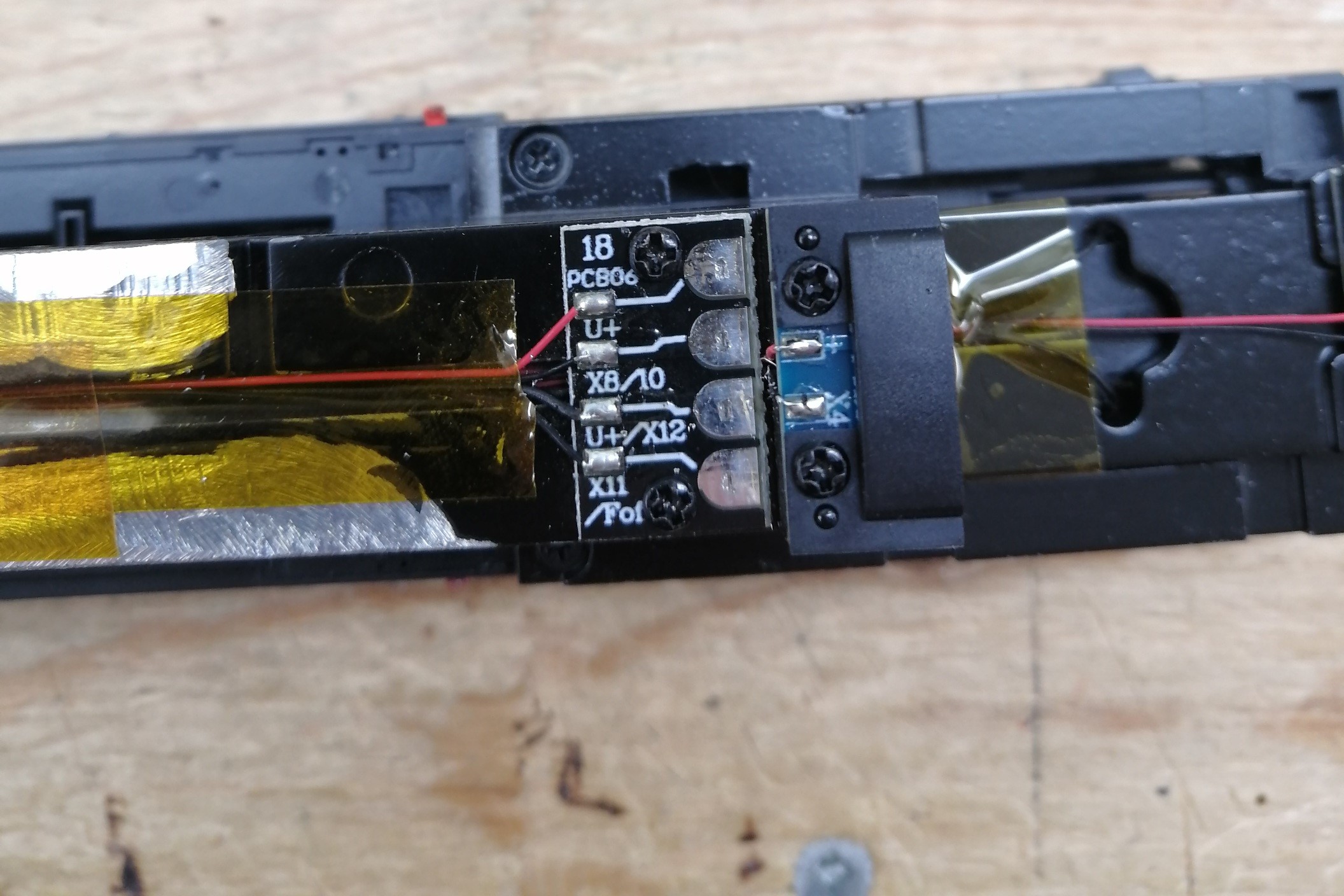
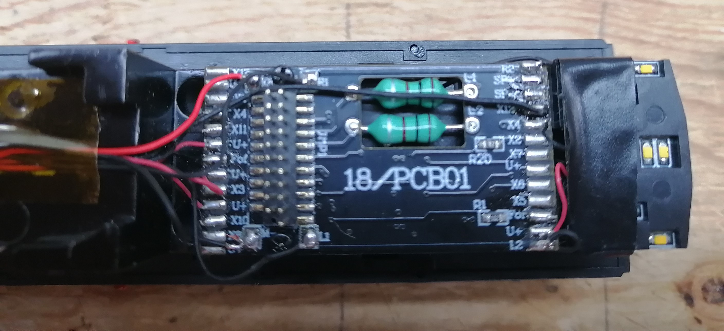
They run to the main board where the 21 pin plug is. U+/X12 is a the far right. NOTE: 21 pin board removed for clarity.
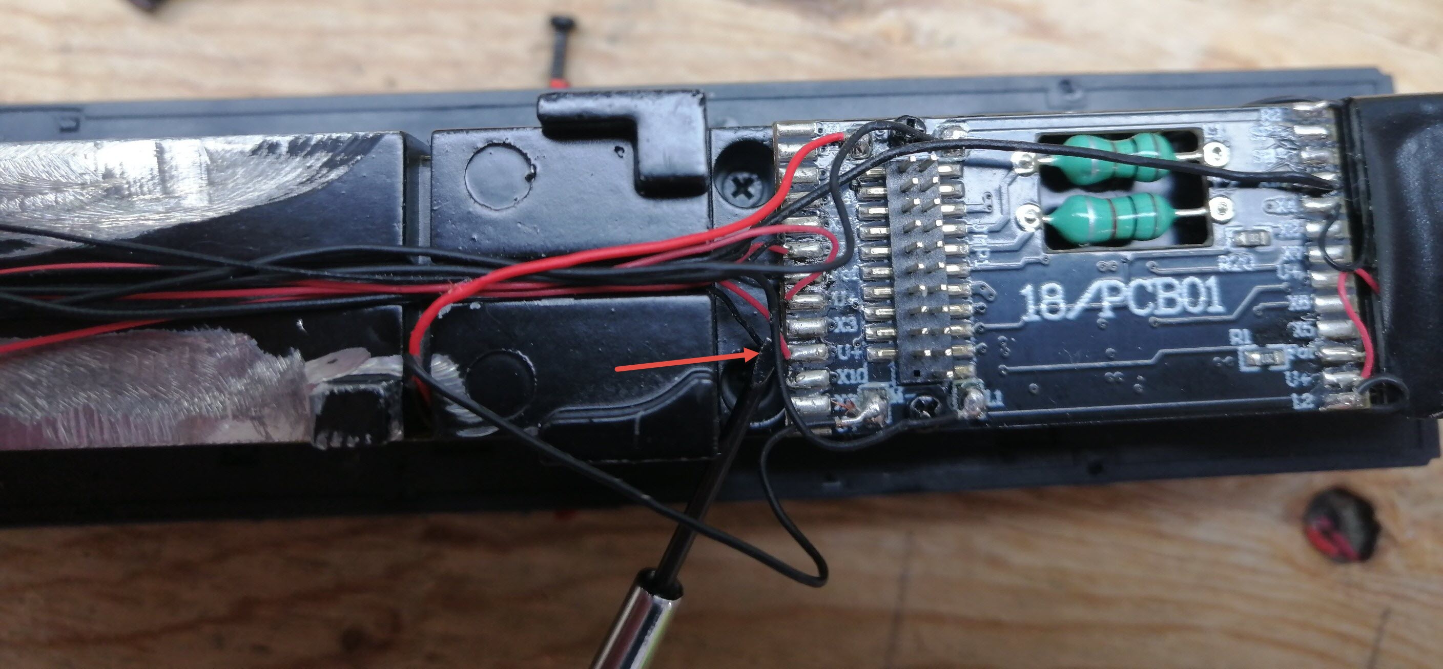
The U+ (red wire) is highlighted here with the screwdriver head and red arrow. X8 is just below X10, which are both below U+ (red wire). X8 is right next to M- which is the black motor wire (M+ red wire is at the top).
Now that we know where the wires go to, is there any magic I can do using the LM-3S to get the Gyralites to work?

